


Document Actions
Tech Tips | MOTU AVB | AVB Routing Tab
AVB Routing Tab...
... An Introduction
 The Routing Tab is one of the four tabs which makes up the MOTU AVB Control Web App, and is used to configure your MOTU AVB interface to route signal to or from:
- your AVB unit's physical inputs and outputs (analog or digital).
- your unit's on-board, 48 channel digital mixer.
- your computer's host audio software, (Digital Audio Workstation) or other audio application.
- other AVB devices on your AVB audio network.
... or any combination of the above scenarios.
This document will highlight the Routing Tab's layout and features, explain the different gestures used to make multiple connections efficiently, and describe steps necessary to establish common routing setups.
Table of Contents
... Jump To What You Need To Know
For a full introduction on the Routing Tab, continue reading. To jump ahead to one of the major sections in this document, use these links:
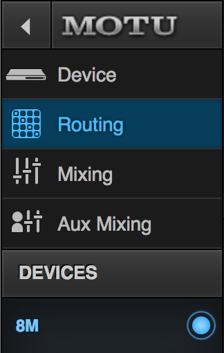
Routing Tab Layout
... Learn the Grid
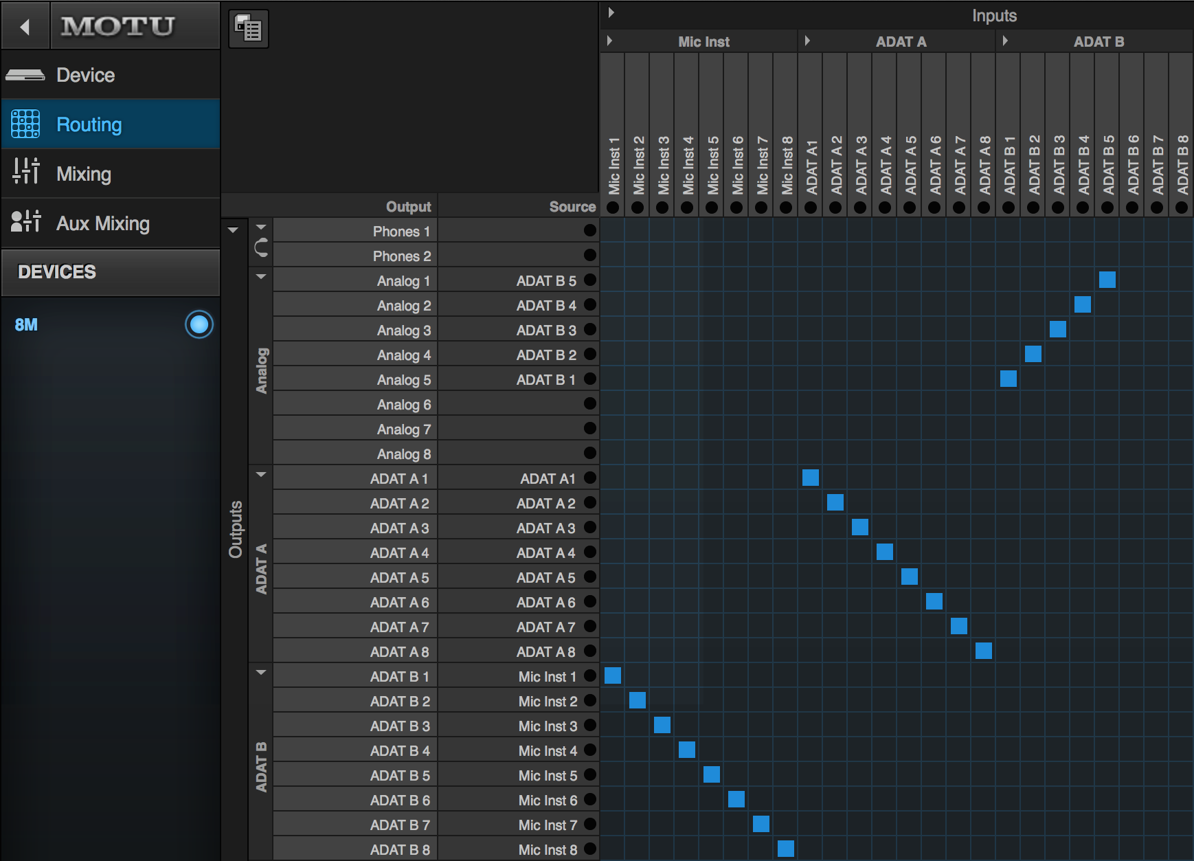
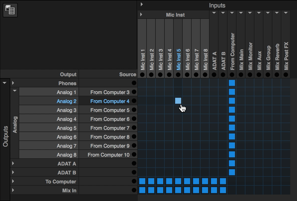
The Routing Tab is laid out as a grid, with inputs listed across the top, and outputs listed on the left. Each I/O type is organized by bank, based on type.
Inputs and Outputs
Inputs are displayed as columns across the top of the routing grid.
The Routing tab will display your unit's inputs in this order (using the 8M's as an example):
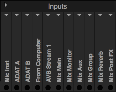
- Your unit's physical Analog inputs.
- Your unit's physical Digital inputs.
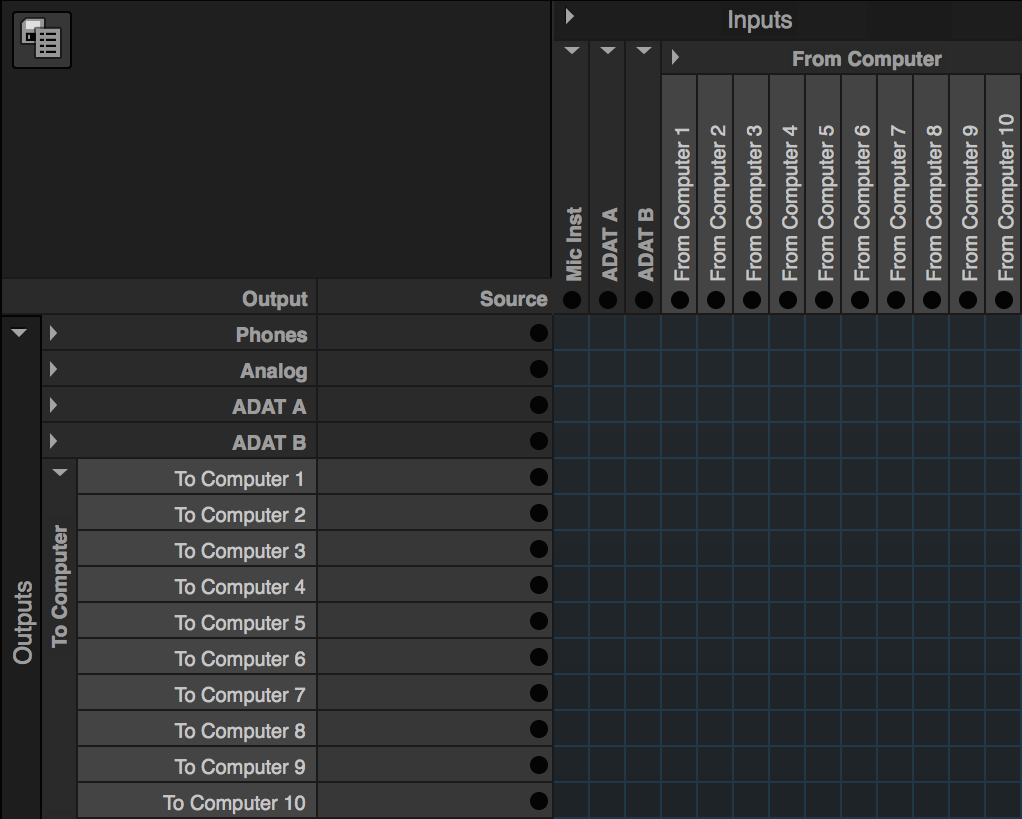
- From Computer audio streams, which carry audio playing from your computer's system output or host audio software. The number of channels within this bank is configurable on the Device tab.
- AVB audio streams, which feed your unit signal from other AVB devices on your AVB network. This picture shows one bank of AVB input streams, but you can add up to 16 banks of 8 AVB audio input channels.
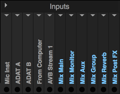
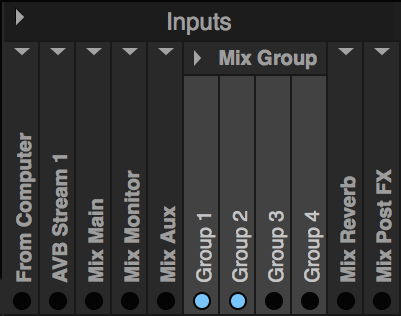
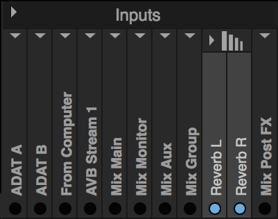
- Mixer Return Busses, which provide returns from your mixer's different output pairs and groupings. These include return busses for the Main Mix, Monitor Mix, seven stereo Aux Mixes (only two shown), three stereo Group Mixes (only two shown), one stereo Reverb bus, and Mix Post FX channel sends for each mixer input channel (only four shown). These channels send signal from your mixer's input channel strip, after being processed by the mixer's effects.
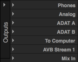
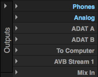
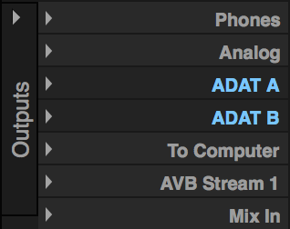
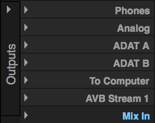
Outputs are displayed as rows on the left side of the routing grid. The Routing tab will display your unit's outputs in the following order, (using the 8M's as an example):
- Your unit's physical Analog outputs.
- Your unit's physical Digital outputs.
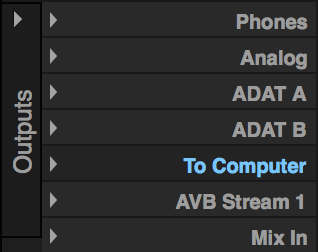
- To Computer audio streams, which are used to send signal from your unit to your host audio software. The number of channels within this bank is configurable on the Device tab, but independent of the number of From Computer channels.
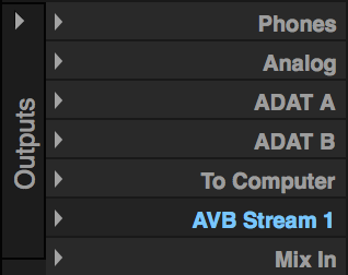
- AVB audio streams, which are used to feed signal to other AVB devices on your AVB network. This picture shows one bank of AVB output streams, but you can add up to 16 banks of 8 AVB audio output channels, (the number of which is independent of the number of AVB input banks).
- Mix In channels, which are used to feed the unit's digital mixer. The amount of Mix In channels is defined by the Mixer Setup section of the Device tab.
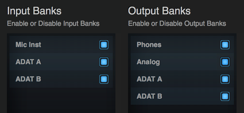
Note: Individual banks of physical inputs and outputs can be toggled on or off in the Input and Output Banks sections of the Device Tab. For example, if you do not see your unit's Analog Outputs in the routing grid, be sure they are enabled in the Output Banks section of the Device Tab.
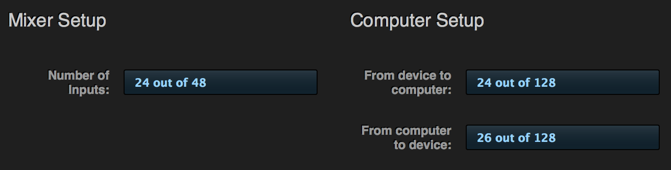
The number of available Mixer channels and To / From Computer audio streams are also customizable at the bottom of the Device Tab, in the Mixer Setup and Computer Setup sections. Setting only an appropriate number of channels for your needs will help consolidate screen-space.
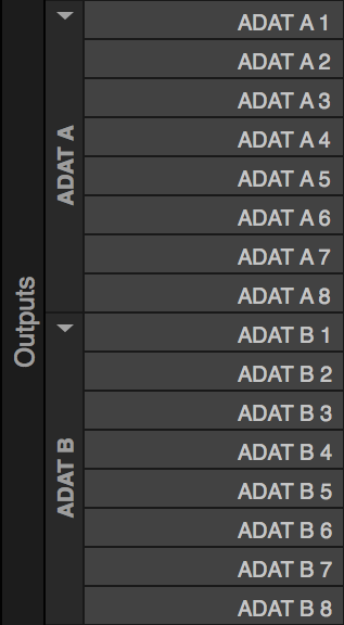
Disclosure Triangles
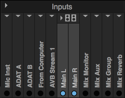
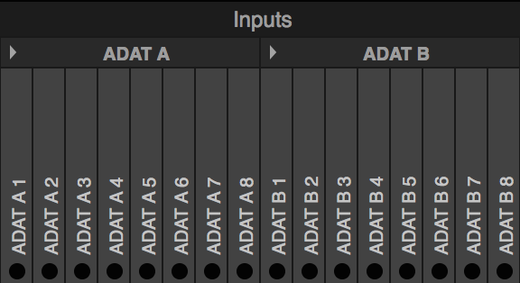
Each input and output bank has a disclosure triangle, used to expand (open) or fold (close) the channels within each bank. Expand a bank to see all of its individual channels (ex: expand the ADAT A Input bank to see all eight ADAT A Input channels, ADAT A 1-8), or fold the bank to consolidate screen-space.
Click To Watch
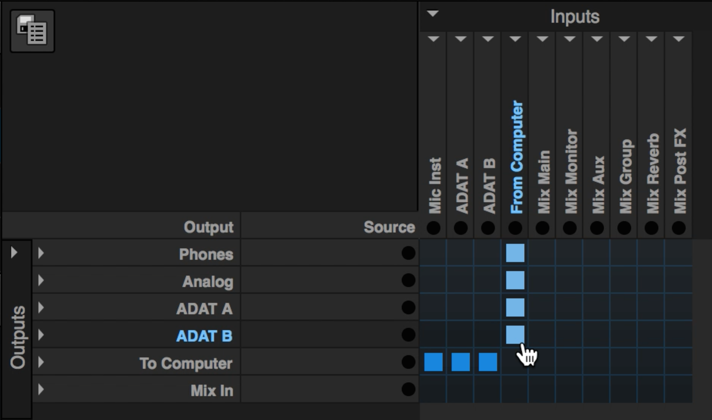
There is a "Master" disclosure triangle for both the Inputs and the Outputs sections, circled in red in the picture below. Clicking it will expand or fold all input or output banks with one click.
Click To Watch
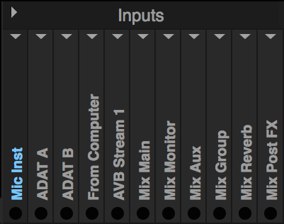
Renaming Channels
When banks are expanded, each individual channel is visible, identified by its default name. To rename a channel, click on a channel's name itself and a text-box will appear. Your custom channel name will replace the default name anywhere this channel is referenced in the MOTU AVB Discovery app. This animation shows how renaming Mic 1 in the Routing page changes the Mixer Input's channel name in the Mixing page. This is helpful in full-mixing situations when you need to quickly identify a channel.
Note: You cannot rename the name of the bank itself. When the bank is folded down, the bank's name appears in place of the individual channel names but is not editable.
Indicator Lights
Each channel has an indicator light. If signal is present at an input, the indicator light will illuminate. If this input is routed to an output, the output indicator light will respond to the same signal.
Click To Watch
If the bank is folded, the bank name assumes the first channel's position, and the one indicator light identifies signal is present on any of the bank's channels. Indicator lights help confirm your signal flow, and can be useful when tracing your signal flow or during troubleshooting.
Making Connections and Placing Tiles
... Routing Inputs to Outputs
Routing a signal is done by clicking on the intersection of a row and column in the grid. When an assignment is made, a "tile" is placed, marking a connection between the intersecting input and output channels. Place a tile, and a connection is made.
The manner in which you make connections on the Routing grid, and how your tile-placing gestures are interpreted, changes if your input and output banks are expanded or folded. Use the tabs below to display details on how the Routing Tab's behavior changes, based on which banks are folded or expanded.
Making Connections and Placing Tiles When...
... Banks are Expanded
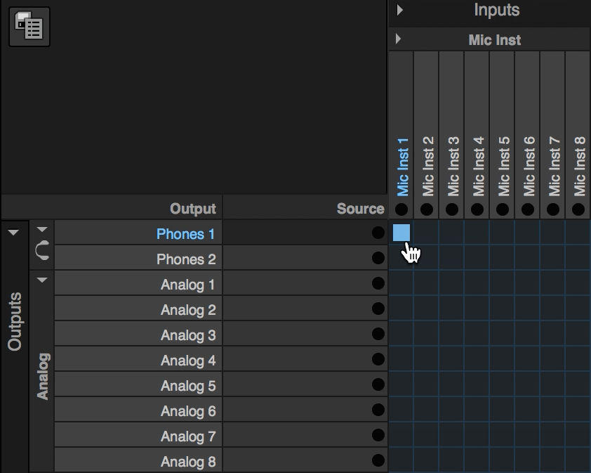
Single Input to Output connections
To introduce making connections, expand your unit's physical input and output banks. A connection can be made with one click at the intersection of two channels. To route a signal coming in from your Mic/Inst 1 input to your Phones, click on the intersection between Mic/Inst 1 and Phones 1.
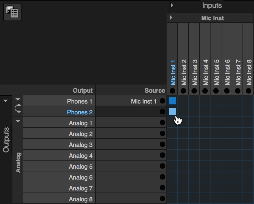
The same input signal can be routed to multiple outputs. Route the same Mic/Inst 1 input signal to both sides of your Phones by making another connection between Mic/Inst 1 and Phones 2, as shown below. Individually click the intersection between Mic/Inst 1 and Analog Output 1 and Mic/Inst 1 and Analog Output 2, and now the same input signal is directly patched-thru to four output channels.
Source
When a connection is made, the name of the input will appear in the "Source" column, to the right of the output channel's name. The text in the Source column is visible if the output bank is expanded, (even if the corresponding input bank is folded). This is handy to confirm which input is feeding a specific output channel without having to trace your tiles.

Remove Connections
To un-do a connection, hover over a tile, and it will turn red. Click once to remove the connection. You can click and drag over tiles established consecutively (vertically, horizontally, or diagonally) to remove them with one click.

Gliding
A common routing need is to route consecutive inputs to consecutive outputs, (Analog Input 1 to Analog Output 1, Analog Input 2 to Analog Output 2, etc.). With both input and output banks expanded, click and place a tile at the intersection of Analog Input 1 and Analog Output 1, and drag diagonally in a South-East direction (down and to the right). Doing so connects each Analog Input to its corresponding output.
Clicking and dragging to make consecutive connections, is referred to as "Gliding". The most common way to use the gliding gesture is to make the diagonal connections discussed above, however you can glide to make different kinds of connections, which will be discussed later.
Click To Watch
When banks are expanded, it is not possible to assign multiple inputs to the same output (create a horizontal line of tiles). Individual output channels can only receive a direct patch-thru assignment from one input channel at a time.
Note: When routing an input directly to an output, your signal will not enter the unit's mixer for on-board effects processing, (this process will be explained later).
Back to top of connections section
... Banks are Folded
Folded Banks
Input and Output banks do not need to be expanded to make connections. Connections can be made, or deleted, when both input and output banks are folded. Click at the intersection of two folded banks, and each input channel in the folded bank will be routed to its corresponding output channel, (Mic/Inst 1 to Analog Output 1, Mic/Inst 2 to Analog Output 2, etc).
Click To Watch
Blue or Green Tiles
Tiles found at the intersection of two folded banks will appear one of two ways. A Blue tile will appear if every input channel for the intersecting input bank has a connection. The most common example would be the South-East diagonal line discussed above, but connections can be made in any order, as shown below.
Click To Watch
A Green tile found at the intersection of two folded banks means not all input channels are connected. Click the picture to see a few other examples, in action.
Click To Watch
If any tile, blue or green, exists at the intersection of two folded banks, one click on the tile will remove all of the connections for the channels within each bank. This is a fast way to clear a bank's worth of connections.
Back to top of connections section
... One Bank is Folded, and the Other is Expanded
If one bank is folded (input or output) and the other is expanded, the gliding gesture provides a new set of results.
Horizontal Gliding
If an input bank is expanded, and an output bank is folded (as shown below), you can glide horizontally across the folded output bank's row to make consecutive connections for each input. The input channel you start with will be routed to the first output channel in the bank, and the direction of your glide determines the order of the rest of the connections.
In the example animation, starting from the intersection of Input 1 and the folded Analog Output bank and gliding to the right, Input 1 will be routed to Output 1, Input 2 to Output 2, etc.

Click To Watch
If you glide from right to left, the results are opposite. The input you start with will be routed to the first output in the folded bank, and as you glide left, consecutive inputs will be connected to outputs in their reverse order. Gliding from right to left produces a South-West diagonal line (from bottom left to top right); Input 8 would be routed to Output 1, Input 7 to Output 2, etc.
Click To Watch
You will find the same behavior if you make connections for only a portion of your input bank; you do not need to be making connections for all channels within a bank. If your glide started at the intersection of Input 3 and the folded output bank, Input 3 will be mapped to Output 1, Input 4 to Output 2, Input 5 to Output 3, etc. After gliding, expand the output bank to observe how this gesture routed your inputs.
Click To Watch
Vertical Gliding
If the output bank is expanded and the input bank is folded, you can glide vertically to produce similar results. In this case, you can glide from the top, bottom, or begin in the middle of an expanded output bank and work in either direction. Gliding from top to bottom will assign the folded input bank's channels consecutively, Input 1 to Output 1, Input 2 to Output 2, etc. Gliding from the bottom to the top will make the reverse connections, Input 1 to Output 8, Input 2 to Output 7, etc.
If you start in the middle, the same connection order follows, with Input 1 being routed to the output channel you clicked on, and successive connections are made following the direction of your glide.
Click To Watch
Back to top of connections section
Common Routing Examples
... How to get from Here to There
The routing examples discussed thus far has used your unit's physical input and output channels as examples for making connections in the Routing tab. However, it is common to find yourself needing to route signal to and from other channels for further usage. Here is a run-down on the Routing Tab setup necessary for other routing purposes.
Sending signal to your unit's on-board mixer
Mix-In Channels
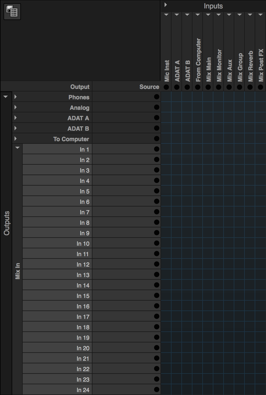
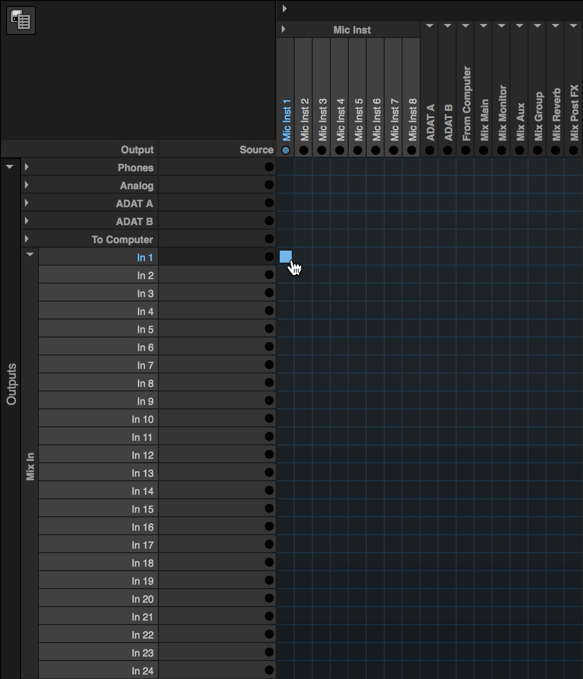
Your MOTU AVB interface is equipped with a 48-channel on-board digital mixer. Much like other large format consoles, setup is required to route signal to and from the mixer. The number of channels in the mixer can be defined in the Device tab (described in the Routing Tab Layout section), and once set, these channels appear as "Mix In" channels, numbered sequentially in the outputs section of the Routing Tab, as shown below.
Keep in mind, these are considered outputs, as the mixer is a destination to which signal can be sent from the Routing tab. This is an important distinction to remember.
Signal coming into your device from any source, (a physical input, a "From Computer" audio stream, an AVB audio stream, or even one of the Mixer's output busses) can be routed to one of the "Mix In" channels. Make a connection on the Routing Tab for an input channel carrying signal, (Mic/Inst 1 in this example) and the Mix In 1 output channel.
Create a Mix in Mixing Tab
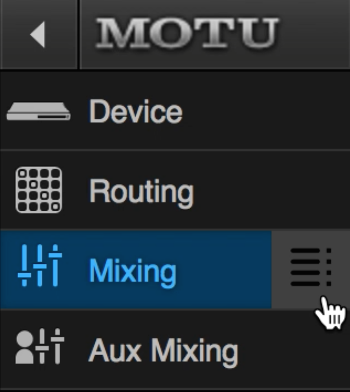
Once done, swing over to the Mixing Tab. To the right of the word "Mixing" is a Mixer Setup menu button (shown left), which will display or hide the Mixing Tab's Setup menu, (shown right). The Mixer Setup menu is comprised of three sections, Controls, Mixer Inputs, and Mixer Outputs.
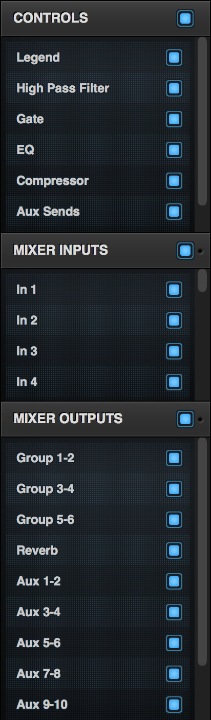
Under the Controls section, you can toggle on or off the Legend, each signal processor, (High-Pass Filter, Gate, four-band EQ, and Compressor), Aux Sends, and Group Sends. Use the Legend button to show or hide the Legend column, which displays each Control's name, information, and additional buttons and settings for the Aux and Group sends.
In the Mixer Inputs section, toggle on the Mixer's first input channel to view its channel strip. This channel will assume the name of the input channel you routed to it in the Routing tab, (Mic/Inst 1, in this case). Successive Mixer Input channels will still be identified by their default name (In 2, In 3, In 4, etc.), if it lacks an input assignment.
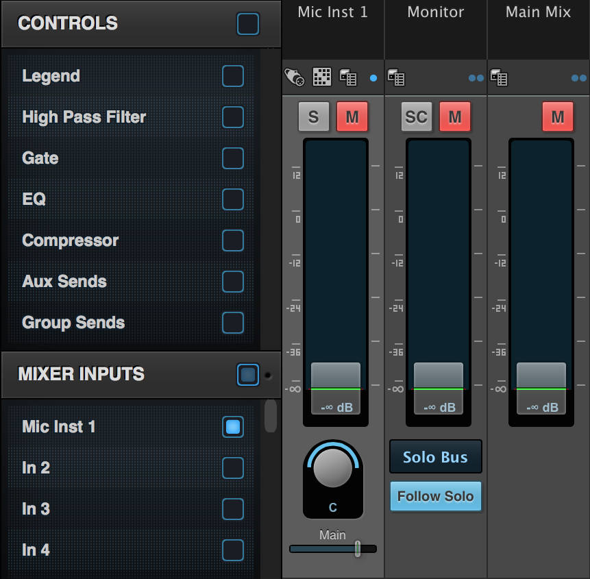
To set up a mix, unmute the Mic/Inst 1 channel, and position its fader. Use the Main Mix send fader below the input channel's pan knob to send your input signal to the Main Mix bus, (it is set to 0 dB by default, shown below), and unmute the Main Mix master fader on the right. Confirm signal is flowing from the Input channel, to the Main Mix master fader.
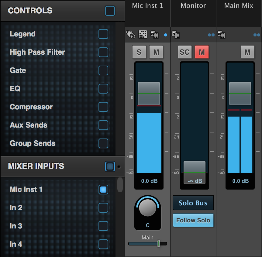
Note: You can not toggle the Monitor or Main Mix channel strip out of view from the Mixer Setup menu. These channel strips are always visible.
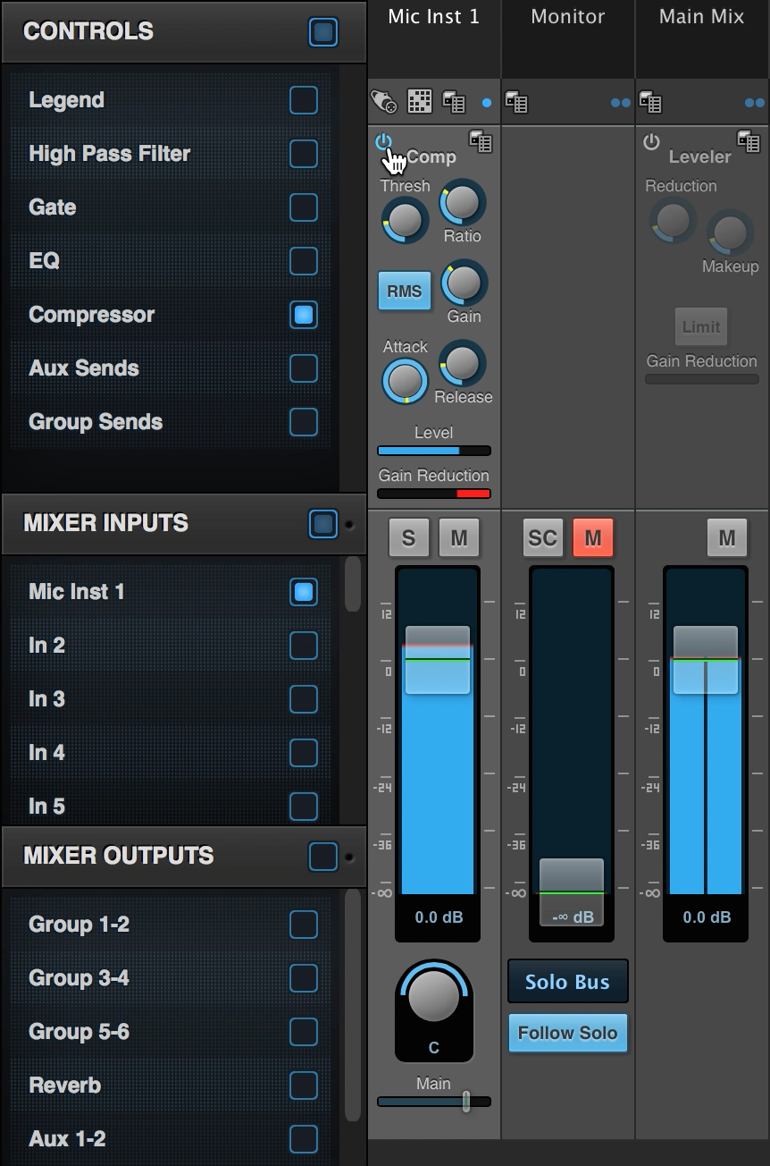
To add signal processing to your mixer's input signal, toggle the desired tool into view from the Controls menu. Once done, its parameters are displayed on your channel strip. Each processing tool has a power button which is used to enable the effect; its parameters will illuminate when enabled.
Your mixer input channel's signal flow follows the channel strip's layout from top to bottom; processing occurs where the signal processor appears on your channel strip. See Appendix C in your AVB manual for full mixer schematics.
Using Aux Channels
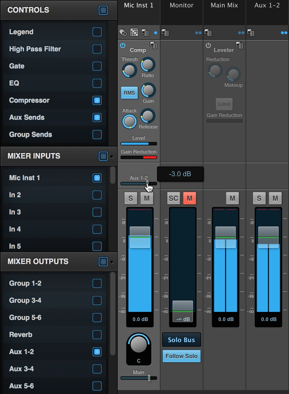
As you display the different Mixer Output channels using the Mixer Setup menu, the corresponding Aux or Group track will appear to the right. On your mixer input's channel strip, you will see the appropriate Aux or Group send fader appear, (if you have Aux/Group Sends enabled in the Controls menu). Toggle the Aux 1-2 channel on, and you will see the Aux 1-2 channel strip appear to the right of the Main Mix channel strip, and an Aux 1-2 send fader appear above the Mute and Solo buttons on your Mic/Inst 1 input's channel strip. (Group sends would appear below the Main Mix send if enabled, not shown in the picture below.) Use the Aux 1-2 fader to send signal to the Aux 1-2 track.
Routing Mixer Return Busses
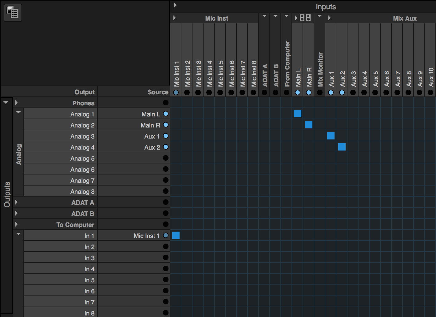
Once input signal is successfully routed through the Mixer, the Mixer's output channel needs to be routed to a destination in the Routing Tab. Keep in mind, the Mixer Output channels, (Main Mix, Monitor Mix, Aux Channels, Group Channels, etc.), are inputs in your Routing Tab, found across the top. Make a connection on the Routing Tab to send the Main Mix bus (Main L/R) output channels to your desired destination, in this case Analog Out 1-2. The Aux 1-2 mix bus also has signal traveling through it, due to the Aux send that was used above, and can be routed to another output as well, Analog Out 3-4 in this case.
These mix busses could have been sent to any other destination, like the To Computer audio streams, your AVB audio streams, or even back into unused Mixer input channels for more advanced routing.
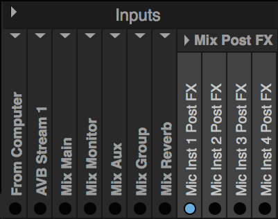
Mix PostFX Channels
The last topic to mention regarding the Mixer Return input banks on your Routing tab, are the "Mix PostFX" inputs. These inputs carry signal from your Mixer's input channels after it has gone through the signal processors on the mixer channel strip, (if none are enabled, this channel will have your original, dry input signal, which could still be split off and routed elsewhere). You can split this signal, post-FX, and send it to any destination.
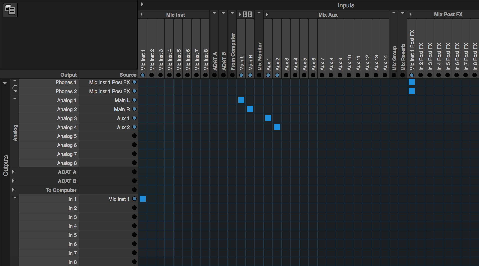
In the example above, dry signal from the Mic/Inst 1 input was sent to the Mix In 1 input channel, where compression was applied. The compressed, wet Mic/Inst 1 signal could be split off, and sent elsewhere, to the Phones outputs, for example. In the picture below, the signal from the "Mic Inst 1 PostFX" mono channel is routed to both Phones 1 and Phones 2 to feed your the processed Mic/Inst 1 signal to your phones.
Jump to top of routing section
Sending signal to your DAW
To Computer audio streams
When using your MOTU AVB interface to record audio in your DAW, you will use the "To Computer" audio streams. Before starting, swing over to the Device tab, and set up your desired number of To / From Computer audio streams (as described in the Routing Tab Layout section). Once set, these channels appear as "From Computer" inputs and "To Computer" outputs in the Routing Tab.
Here is a list of your unit's physical input and output count (when operating at 44.1 or 48 kHz sample rate). If your AVB unit is connected via Thunderbolt, and you are running at 1x or 2x sample rates, use these numbers as the minimum number of To and From Computer audio streams when recording in your DAW:
- 1248: 32 inputs / 34 outputs
- 8M: 24 inputs / 26 outputs
- 16A: 32 inputs / 32 outputs
Note: If you are connected to the computer via Thunderbolt, you have access to 128 To / From Computer streams if operating at 1x or 2x sample rates (44.1 kHz - 96 kHz). If you are operating at 4x sample rates (176.4 kHz or 192 kHz), you have access to 64 To / From Computer streams.
When connected via USB, you have access to 24 To / From Computer streams regardless of the sample rate.
To / From Computer routing
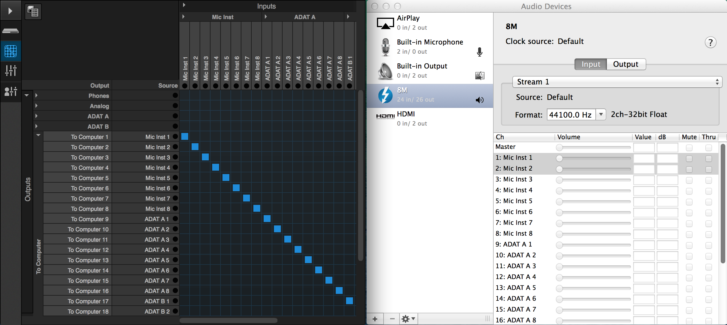
Conventionally, it is desired to have each physical input on your AVB device routed to its own independent "To Computer" audio stream. Using the techniques discussed above, fold the "To Computer" output bank, and the input banks for the physical inputs you are recording in the Routing Tab. Glide horizontally across the input banks you plan to record, along the To Computer row, to make the appropriate connections. If you enabled enough To Computer streams in the Device tab to cover all of your physical inputs, you can make connections with one gesture. (If you didn't enable enough, you may be left with a Green tile at the end of your row, denoting the last bank lacks a complete set of connections).

Repeat the same process to route the "From Computer" input streams to your unit's physical outputs, or any other set of output channels you want your DAW's playback to be sent. For example, in the Routing Tab, fold both the From Computer input column, and the output rows for your unit's physical outputs, and glide from top to bottom. Doing this, each From Computer output stream is routed to its own physical output on your unit. You also have the option to feed your DAW's output to your AVB audio streams or your unit's on-board mixer and utilize your unit's signal processing tools. To do so, make a connection to route the From Computer stream to a "Mix In" output, or AVB output stream.
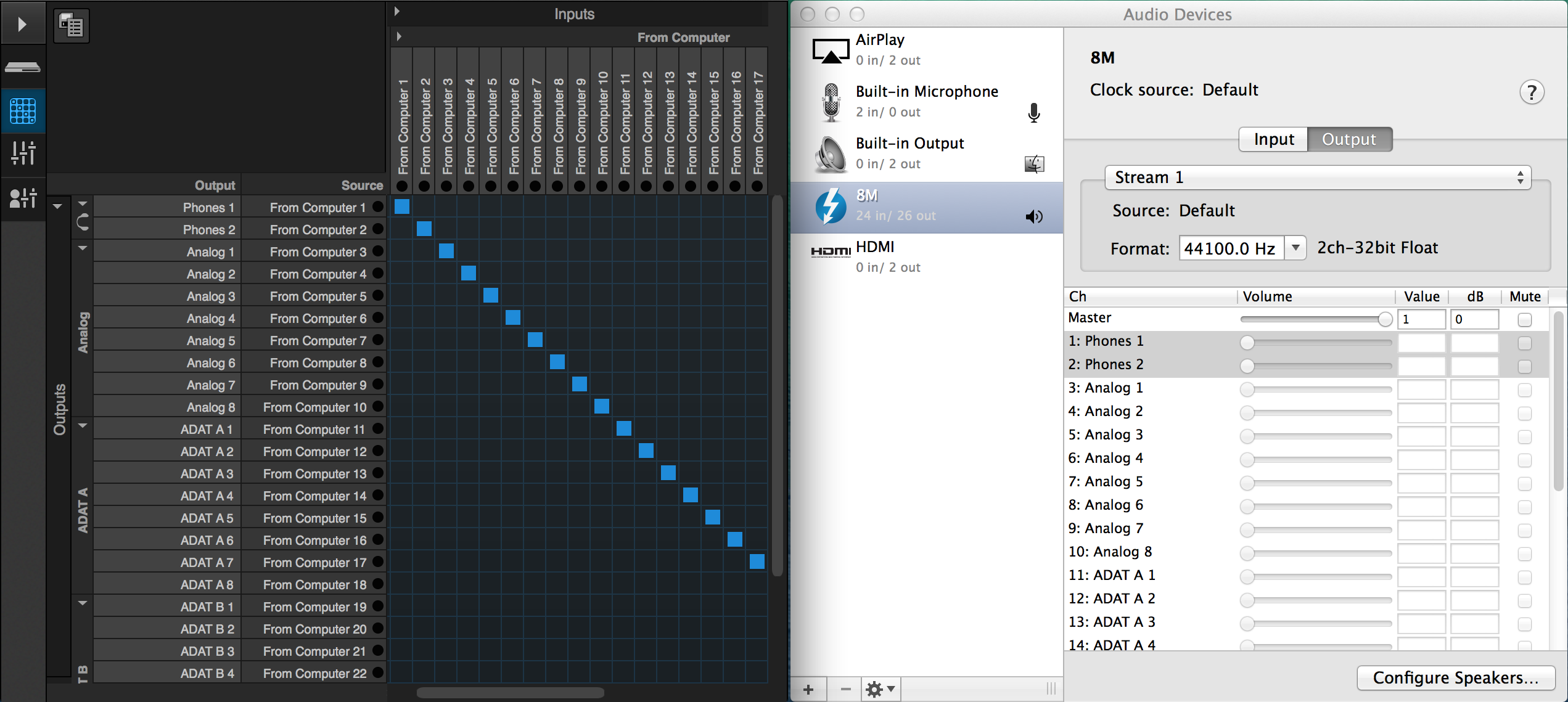
To / From Computer channel names
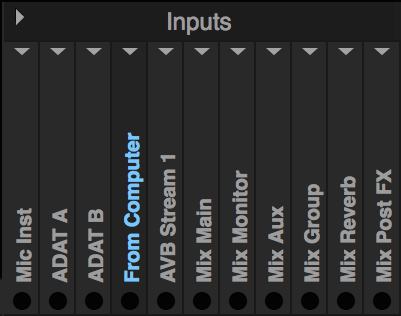
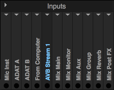
If your AVB device is connected to Mac OSX via Thunderbolt, you can see your unit's channel names in the Audio Devices window of the Audio MIDI Setup. When no connections are made for the To or From Computer audio streams, the input and output channel names will be listed by their default names, (In 1, In 2, Out 1, Out 2, etc.). When a connection for these channels are made in the Routing Tab, the Input and Output channel name will update in the Audio Devices window. Here is how your Inputs and Outputs tabs will look in the Audio Devices window after routing the To and From Computer streams.
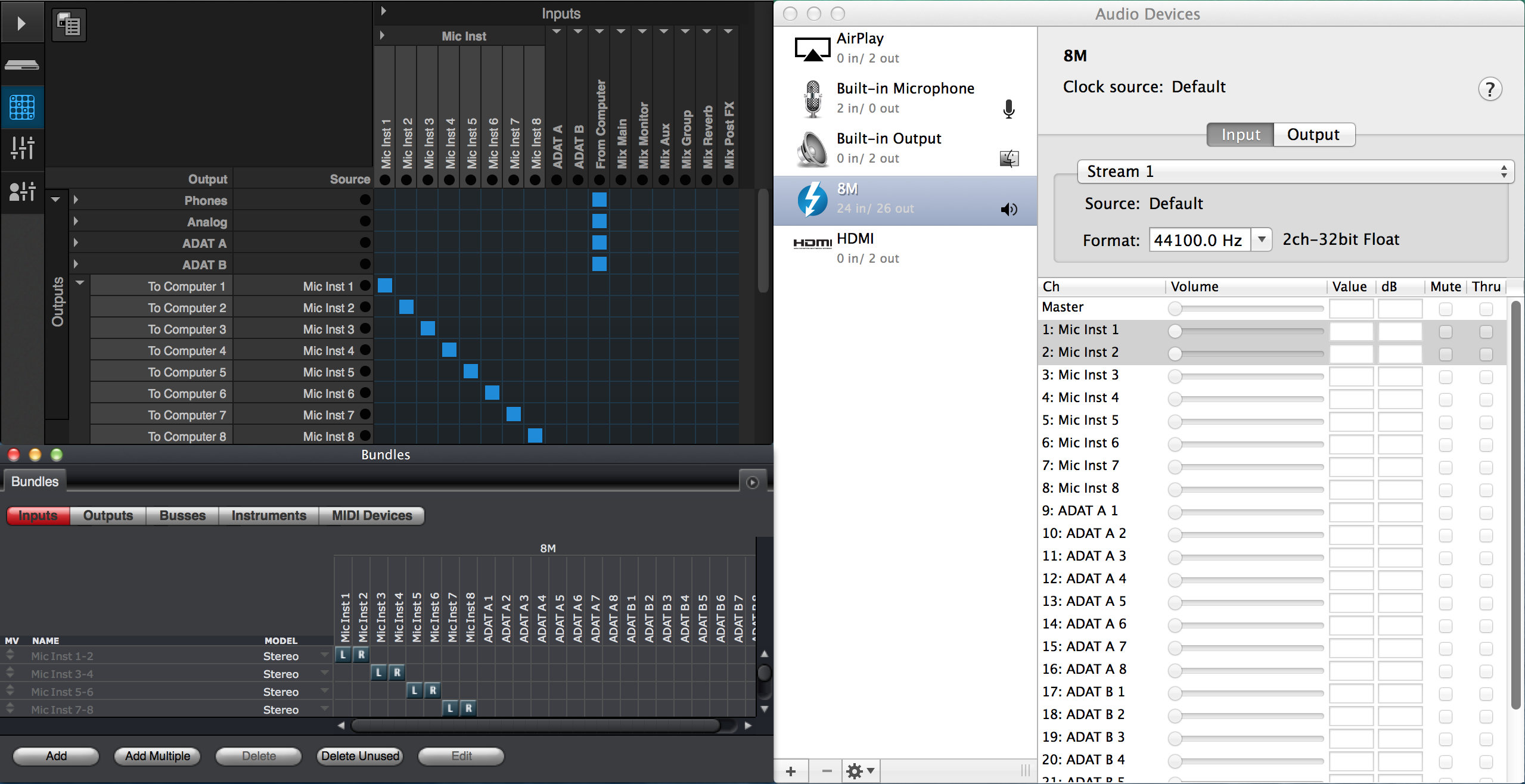
Digital Performer will also show these updated channel names automatically when To/From Computer connections are made or removed. For example, when viewing the Bundles window in DP8, the column headers for the Inputs and Outputs pane will reflect the channels that are connected to the To / From Computer audio streams in the Routing Tab of the AVB Discovery web app.
If your DAW does not utilize CoreAudio dynamic naming, the channel names will not update within the application when making these connections, like they do in Digital Performer. The default To/From Computer audio stream names will remain, Audio In 1, or Audio Out 1, etc. In this case, it may be best to keep the Audio Devices window of the Audio MIDI Setup open for reference.
Note: When your device is connected to your computer via USB, the names of the To/From Computer audio streams will not update when these connections are made. In this case, channels will always be displayed as Audio In 1, or Audio Out 1, etc.
Advanced To / From Computer routing
It is possible to route the same physical input to several To Computer audio streams. In doing this, the physical input name would appear multiple times for each To Computer audio stream, as shown in the Bundles window of DP. Doing this, these To Computer audio streams would be carrying the same input signal, which could be recorded simultaneously on multiple tracks in DP.

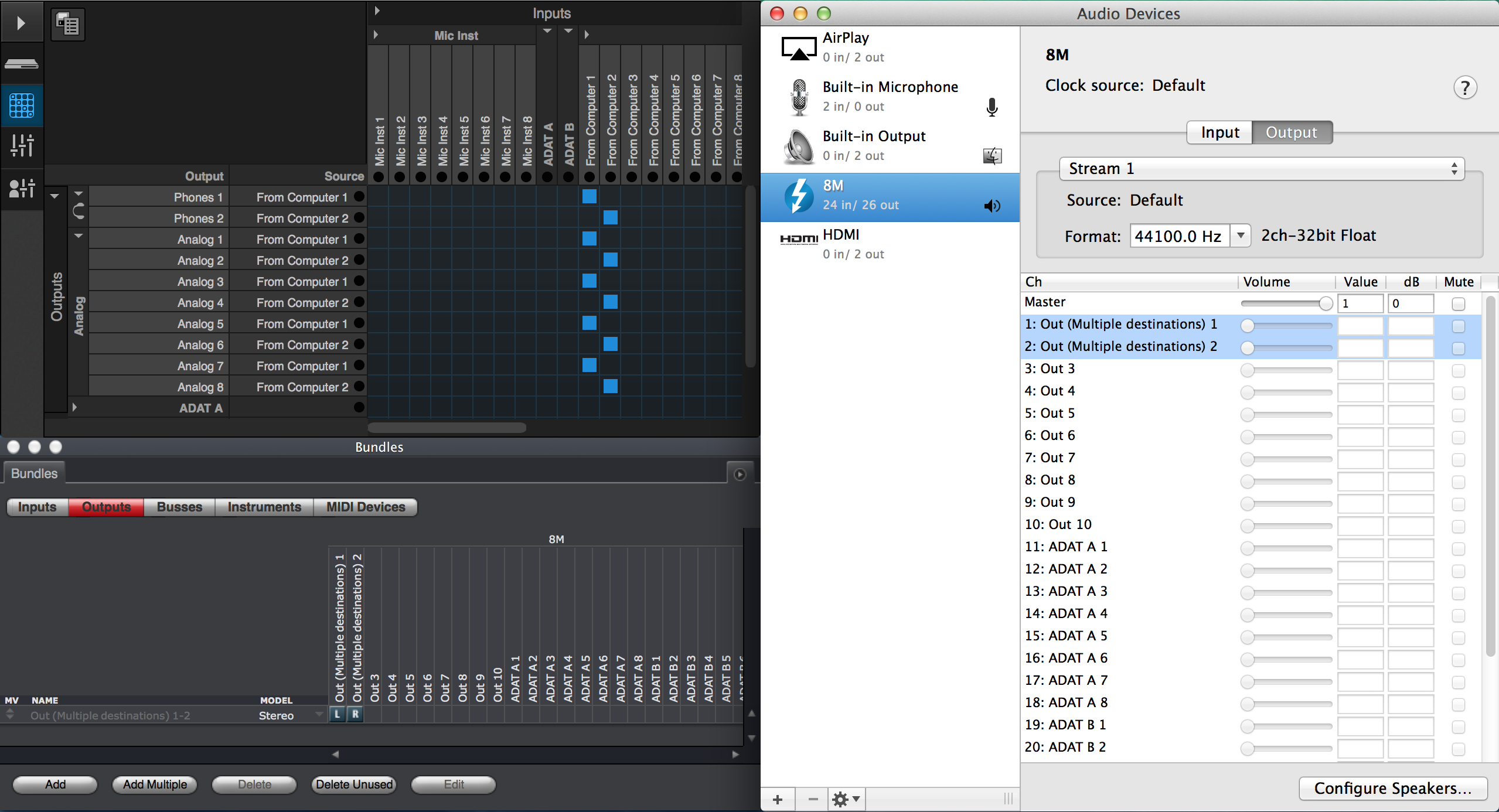
Conversely, the same From Computer audio stream can be routed to multiple destinations simultaneously in the Routing tab. This is helpful in situations where you want an output bundle available for your audio tracks in DP, all of which will send the same signal to multiple outputs on your device. When assigning the From Computer 1-2 input channel to Phones 1-2, Analog Out 1-2, and Analog Out 3-4 output channels in the Routing tab, these audio streams would be renamed to "Out (Multiple Destinations) 1-2" (as shown in the Audio Devices window of the Audio MIDI Setup, or the Bundles window of DP8) and will feed the same signal to all three physical outputs pairs at once.
Jump to top of routing section
Sending Computer's audio to physical outputs
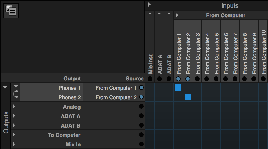
When your AVB interface is set as the device for your system's sound output, audio playing back from an application like iTunes, or media streaming from your web browser, will be sent to your unit through the From Computer 1-2 audio stream. As you play audio, you will see the From Computer 1-2 indicator lights illuminate. Make a connection to your unit's physical outputs, (Phones 1-2, or Analog 1-2) to send audio to your headphones or speakers.
If it is necessary to change which "From Computer" audio stream your system is using for playback, right-click on your AVB device in the Audio Devices window of the Audio MIDI Setup, and click "Configure Speakers". Select the Stereo button and click the Stream you want to use from the list above (be sure to deselect the original stream, as when clicking Apply, only the first checked stream will be used). Confirm the corresponding channels are assigned to the "Left Front" and "Right Front" drop-down menus in the graphic below, and click "Apply" to submit these changes.
As discussed, your computer's playback can be fed to your unit's on board mixer, or sent to an AVB audio stream as well.
Jump to top of routing sectionSending signal to AVB audio streams
To send audio to other devices on your AVB network, you will use the AVB audio output streams in the Routing Tab when making connections. To explain basic AVB routing, we will use the following example:
- An 8M is being used as the master device, and is connected to the computer via Thunderbolt.
- The 8M is connected to the MOTU AVB Switch via an CAT-5e Ethernet cable.
- A 1248 is connected to a second AVB Network port on the same MOTU AVB Switch, and will be the second unit on the AVB network.
The goal is to play audio in iTunes through the 8M, and route the signal to the 1248 via an AVB audio stream. Set the 8M to be the device for your system's sound playback from the Audio MIDI Setup, or the Sound page in your System Preferences.
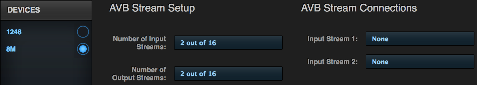
Power both units on, and confirm they are both listed under the Devices menu in the MOTU AVB Discovery web app. Go the 8M's Device tab, and under the AVB Stream Setup section, set the Number of Input and Output Streams to 2, (shown below). Go to the 1248's Device tab, and repeat the process. Keep in mind, "2" is just being used as an example. You need to enable at least one stream for AVB routing, but you could enter any number between 1 and 16. Each stream adds an eight-channel bank of AVB audio streams to your device's Routing tab.
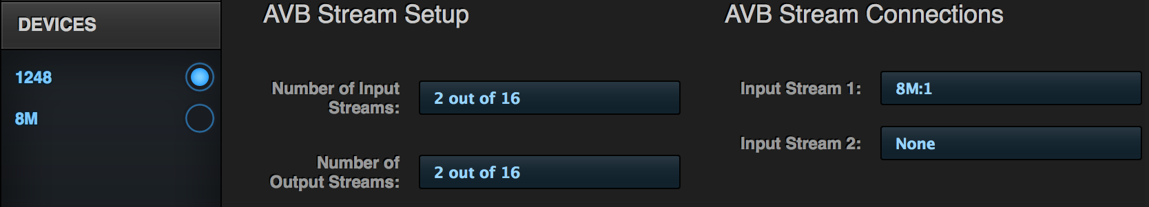
While on the 1248's Device tab, assign the AVB Input Stream 1 to "8M:1". This establishes which AVB stream on the network will be fed to the 1248's AVB input bank #1.
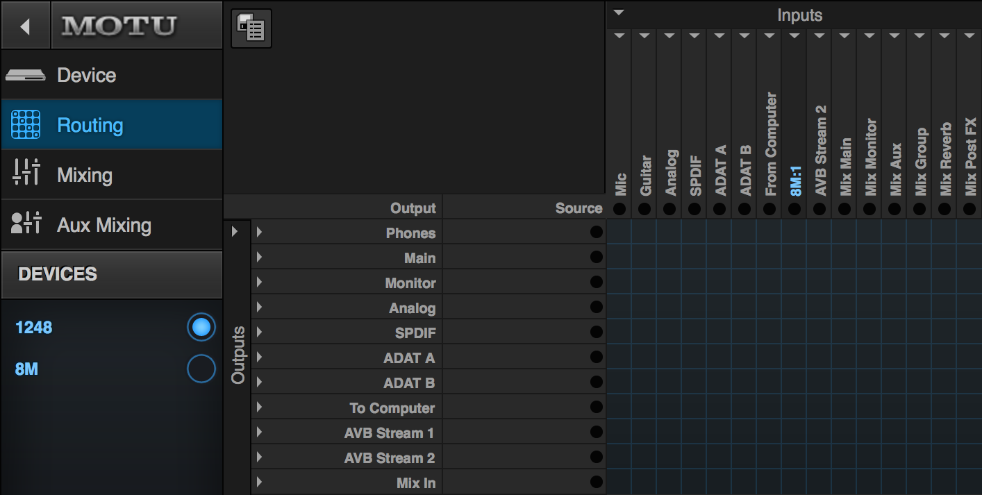
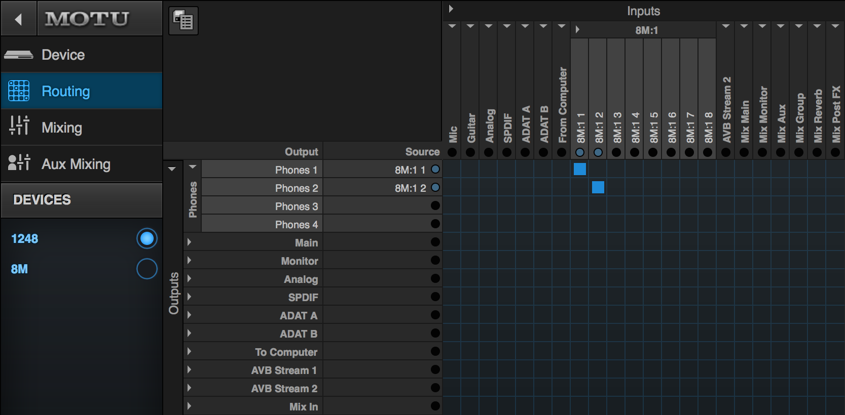
To see where this changes things, go back to the 1248's Routing tab and you will see AVB Stream 1 input bank is now renamed to "8M:1".
Note: Only the bank names for AVB Input streams will update when making changes in the AVB Stream Connections section. The AVB Output streams of your primary device will not change names, and are always displayed by their default name, "AVB Stream 1", etc.
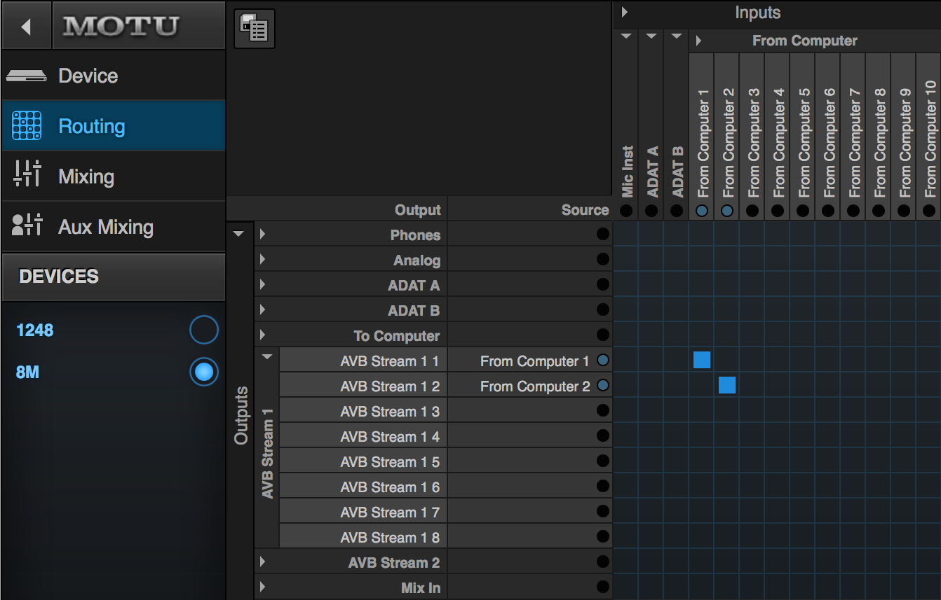
To establish the signal flow for your iTunes to travel from the 8M to the 1248, go back to the 8M's Routing tab, and make a connection between the "From Computer 1-2" input channels, and your "AVB Stream 1 1-2" output channels. Play audio in iTunes to confirm signal flow between these two channels using their indicator lights.
Swing back over to the 1248's Routing tab. The first two channels in the 8M:1 AVB Input bank should be showing the same signal activity on their indicator lights. This confirms signal has been received by the 1248. Make a connection between these two channels, and the Phones 1-2 output channels to send audio to the 1248's first headphone jack on the front panel.
Jump to top of routing section
Do you have a question or comment about this document? Or perhaps, a suggestion on how to improve it? We'd like to hear from you. Please, write us here, and let us know what you think. Thanks!