


Document Actions
Tech Tips | CueMix FX | Audio Analysis Tools Part Two - Oscilloscope

CueMix FX Audio Analysis Tools Part Two: Oscilloscope
The latest models of MOTU FireWire/USB/Thunderbolt (non-AVB) audio interfaces are built with CueMix FX, which includes expanded mixing and signal processing features. Additionally, CueMix FX units have several handy audio utility tools (found under CueMix's Devices drop-down menu) designed to help you analyze any input, output or mix bus's signal. We'll take a look at each of these in this five part series.
The Oscilloscope audio analysis tool works just like other standard Oscilloscopes, plotting amplitude of an audio signal over time. Just like the FFT Analysis window, the Oscilloscope will analyze whichever stereo input, mix bus, or output channel pair is in "Focus". Use the Focus button above each channel in the main CueMix window to change the display. Keep in mind, even if the "Focused" channel is a mono input, the Oscilloscope will display its paired channel as well.
The Oscilloscope can be resized to fit your full screen by clicking and dragging on the bottom right corner. The right panel has several controls to help configure and adjust the positioning of your Oscilloscope, View, Horizontal, Vertical, and Waveform Recognition.
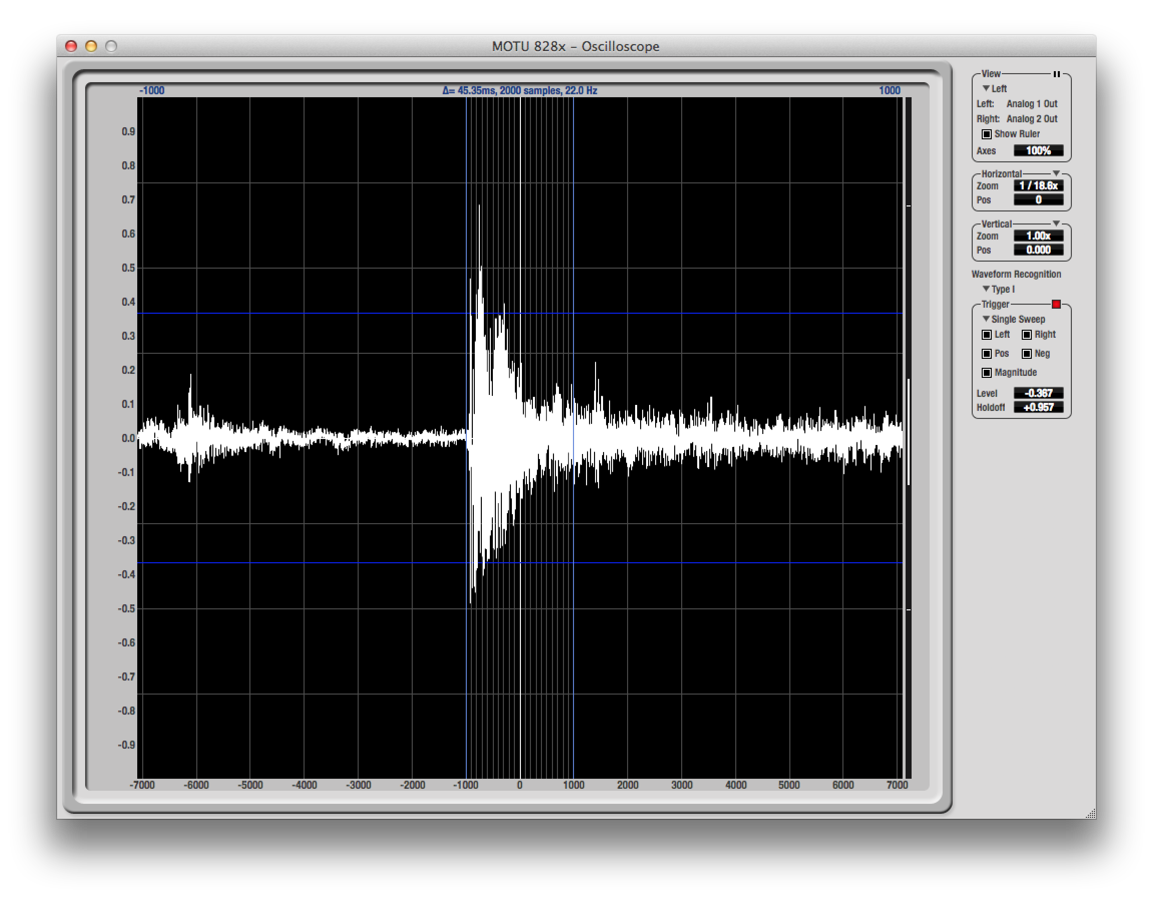
Starting with "View", there is a triangle disclosure drop-down menu where you can select the view type, with the following options; Left, Right, Split Screen, Shared, Add, Subtract. Use the Left or Right options to view one channel at a time, as shown below in this picture.
Split Screen will provide a stereo view, with the left channel on top and the right channel on the bottom.
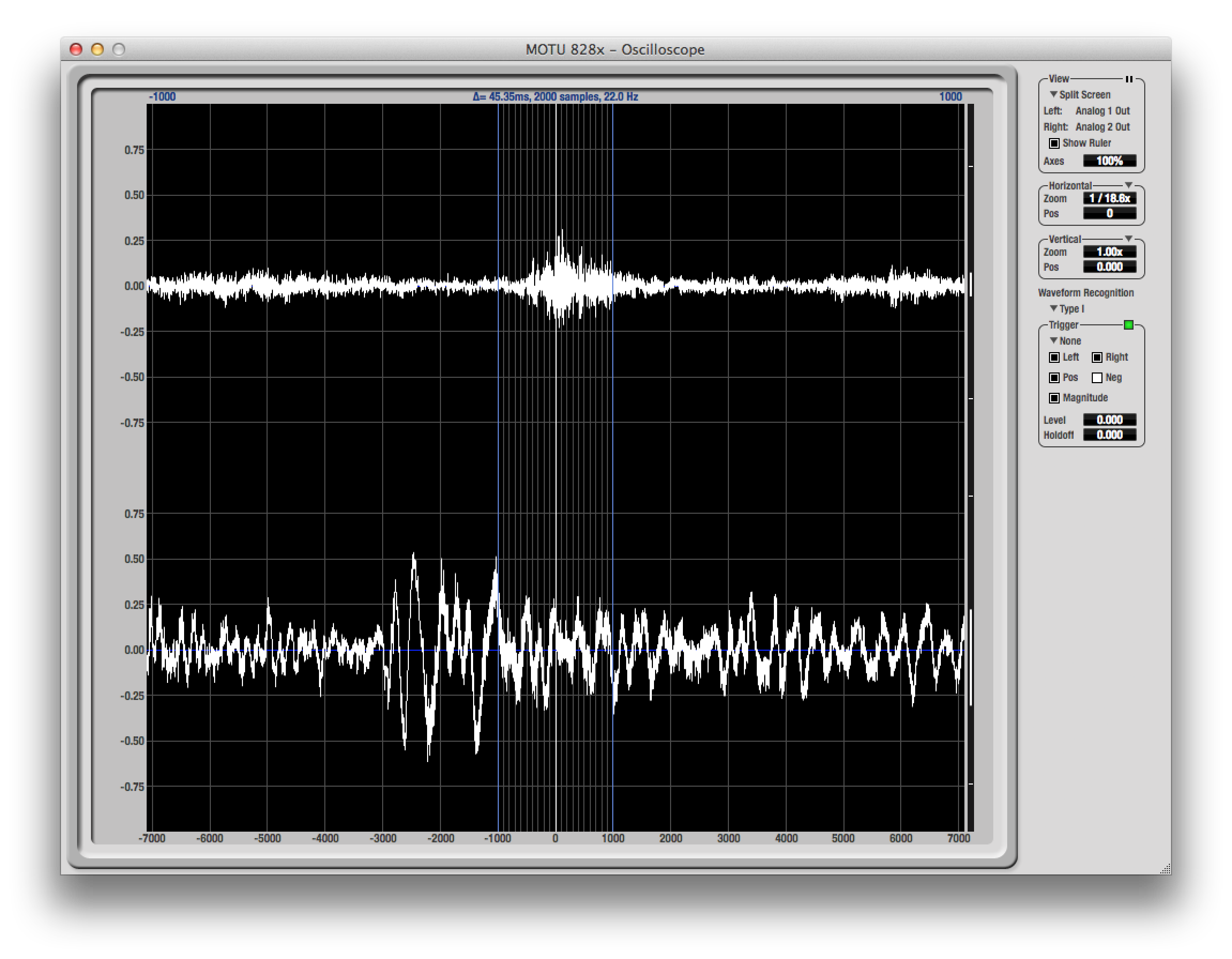
Note: Split Screen is the only View type to change the vertical range of the Oscilloscope, as the same +1 to -1 range is shown twice, once for the left (top) channel, and once for the right (bottom) channel.
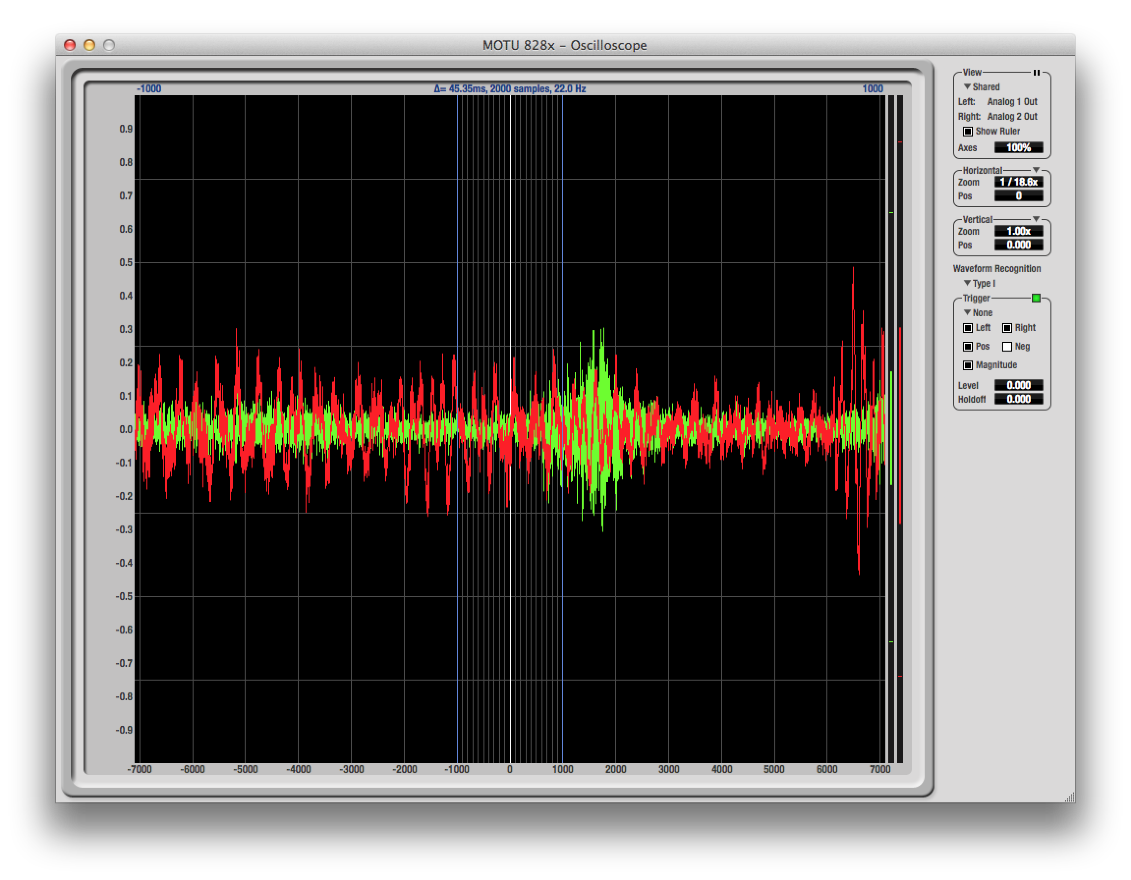
Shared will superimpose both left and right channels on top of each other, with Green indicating the left channel and Red indicating the right.
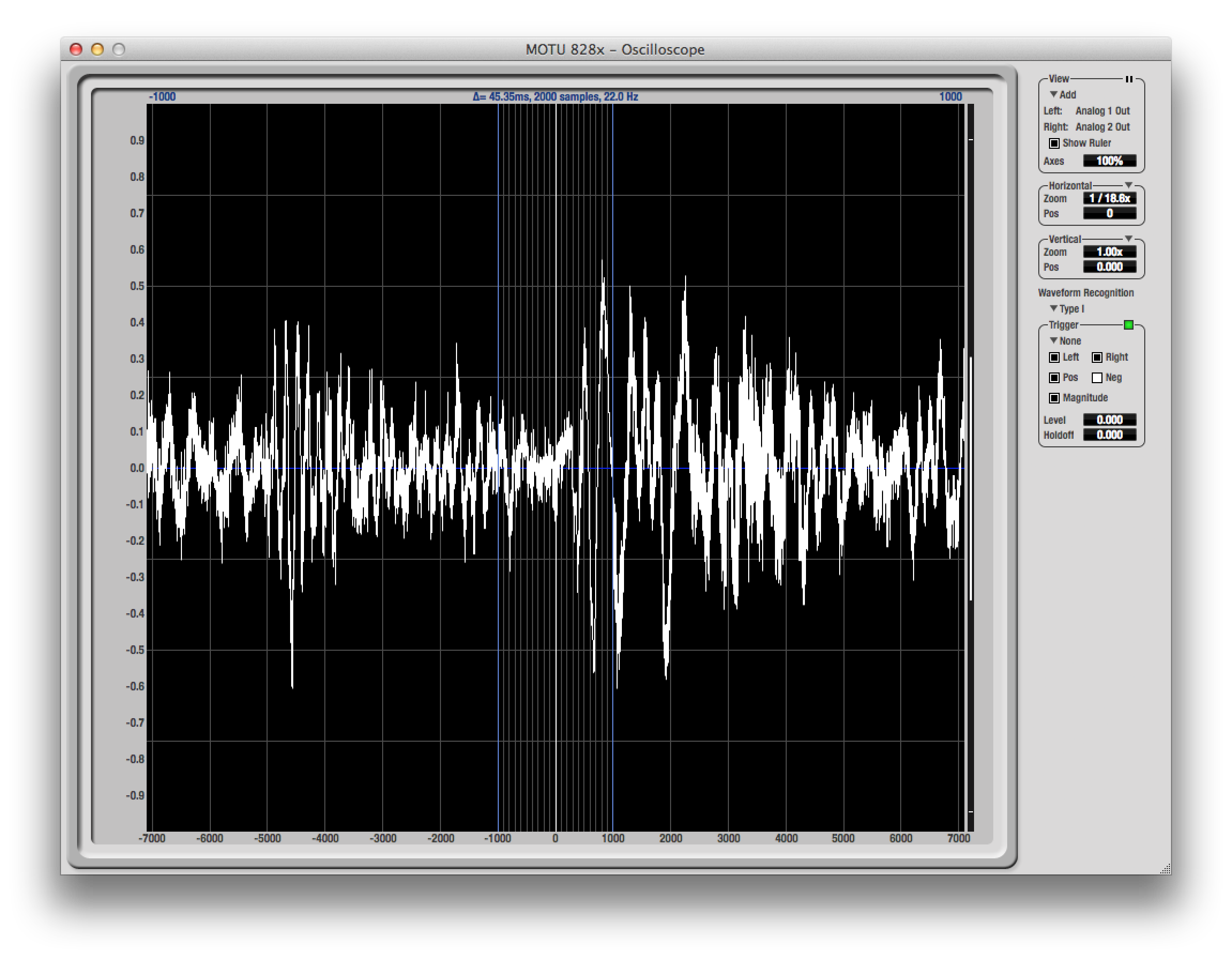
Add and Subtract will show one resulting waveform of the implied operation; Add shows the amplitude of the left and the right channel added together (picture shown below), and Subtract shows the resulting waveform when the right channel's amplitude is subtracted from the Left.
To the right of the word View is a pause button, which freezes the current Oscilloscope view until you click again to resume. While paused, the level meters on the right vertical axes will still be measuring any present signal. Pausing the view is excellent for taking measurements, etc.
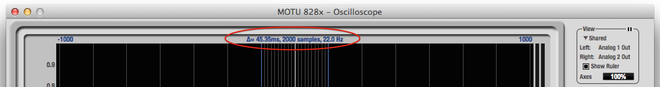
The Show Ruler box toggles the Measurement Information Bar, and the two vertical blue measurement lines on or off. These lines can be placed at the beginning and end points of any area you wish to measure. When adjusting their positioning, the Measurement Information Bar will update to show you the length of time (Δ), the number of samples, approximate frequency, and the scientific note name of the selected range. If the measured area is long enough, the approximate beats per minute (bpm) is also displayed. You can also click and drag the blue numbers above the measurement lines up or down to change the measurement area's range. To reset the lines' positioning, double click its corresponding number.
The last View setting is the Axes control, which sets the opacity of the axes, with 100% being fully visible, and 0% being hidden.
The next two sections, Horizontal and Vertical provide settings to adjust the Zoom and Positioning of your Oscilloscope's view.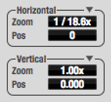 The Horizontal settings configure the x-axis (time), and the Vertical settings configures the y-axis (amplitude). Each value can be clicked and dragged vertically to scroll through different settings, and double-clicked to return to its default value. The triangle drop-down menus to the right allows you to switch these controls from Zoom and Pos (identified in the menu as Zoom/Offset) to Minimum and Maximum. At the bottom of the Horizontal section's drop-down menu is an addition setting to change the x-axis's unit from Samples to Seconds. Your hardware's manual provides detailed information on the different Zoom/Position settings and ranges.
The last section is the Waveform Recognition section. Using the Waveform Recognition's Trigger settings, you are able to configure how, and when, the Oscilloscope's view updates, based on the signal being passed through it. There are two types of Triggers. Type 1, provides the most stable type of display for the waveform and is most resistant to change. In most situations, this is best suited for observing cyclical signals, like the shape of a synthesizer or the processed tone of a Guitar input after passing through a chain of pedals. Type 2 is better suited for signals with loud transients, as it is less resistant to change.
 Under the word Trigger is drop-down menu to set the Trigger type. "None" means the Trigger is off, the Oscilloscope's view will update automatically, in normal fashion."Auto" means the Trigger will update automatically, regardless of the amplitude of your signal, every time the Trigger "re-arms". This "re-arming" period is defined by the Holdoff setting, which is a time value; if the Holdoff is set to +1.000 (1 second), it takes 1 second for the Trigger to re-arm, and every second, the Oscilloscope's view will update. While the Trigger is re-arming, the Green box to the right of the word Trigger will turn Red. When the Holdoff time has finished, it will return to green, meaning it is ready for the next event that meets the Trigger's conditions; when using the "Auto" Trigger type, it will have an instantaneous response, and will automatically re-trigger, and the box will immediately return to red.
The "Normal" Trigger type will also respect the Holdoff time, but takes into consideration the other criteria in the Trigger menu, (highlighted in red on the right).
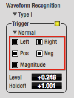 Use the "Level" setting to define the amplitude threshold of the Trigger. Checking the "Magnitude" box mirrors your level setting so both positive and negative values are considered.
The remaining checkboxes assign what audio channel and direction of the amplitude's slope the Trigger is looking at. The Left and Right checkboxes refer to the left or right channel of the audio signal (at least one channel needs to be engaged to have something for the Trigger to look at; both can be engaged if desired). Pos and Neg checkboxes refer to the slope of the amplitude the Trigger is looking for, with Pos being used for increasing amplitude, and Neg being used for decreasing amplitude (again, at least one type needs to be engaged for the Trigger to have something to look for; both can be engaged if desired).
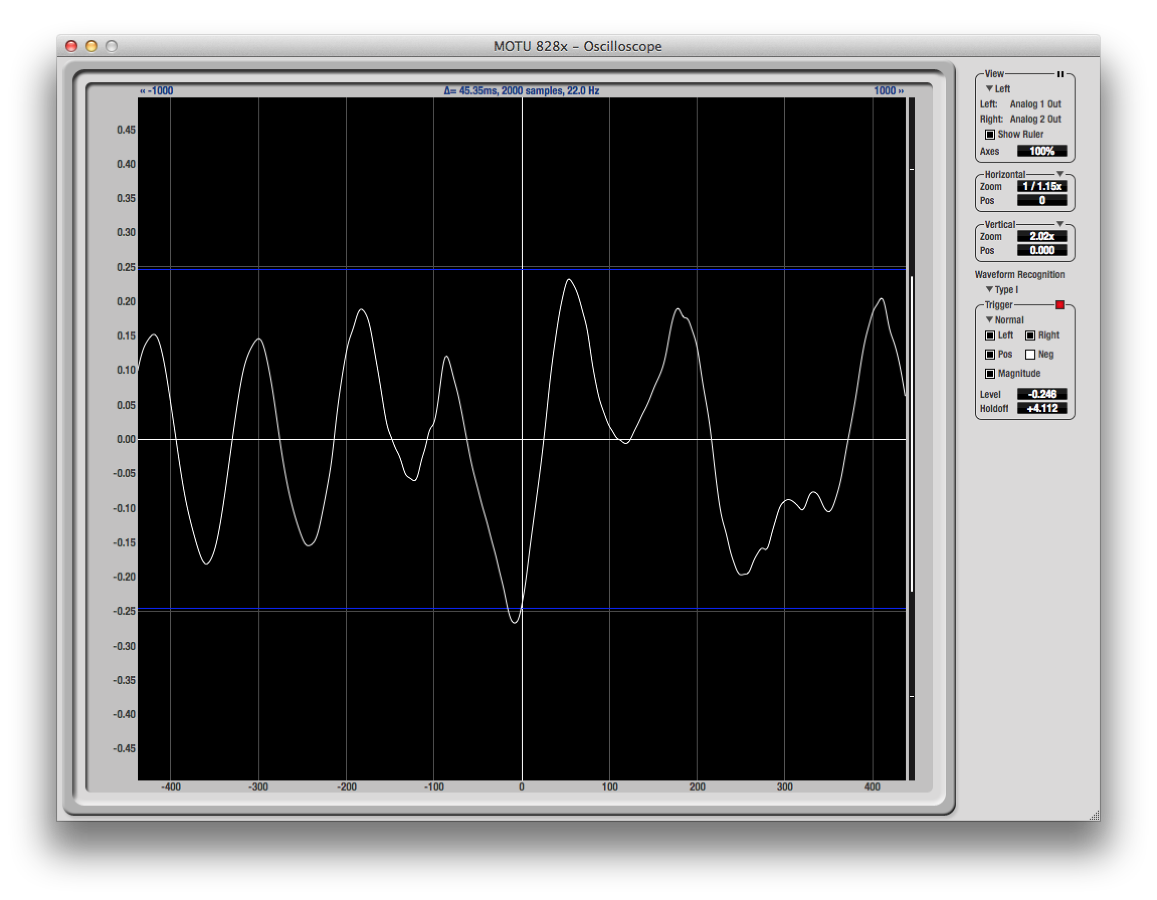
The picture below shows where the Trigger identified a positive-sloped amplitude crossing the threshold. (In this case, the Magnitude box was engaged, making both +/- .246 acceptable threshold values. The Trigger was set off because the increasing amplitude of the signal crossed this negative level threshold. Notice how the Trigger was not set off when the signal crossed the threshold while its amplitude was decreasing.)
When the "Normal" Trigger is ready, the colored box will be Yellow. Once these conditions are met, the "Normal" Trigger will freeze the waveform display, and the box turns Red. The box remains red until the Hold-off time has passed, then it is refreshed to yellow to indicate it is ready for the next matching event. Clicking the colored box will reset the Trigger's Holdoff time; clicking and holding the colored box will bypass the Trigger. When held, the box is green.
"Single Sweep" mode is very similar to "Normal", except you have to manually reset the Trigger. When the display freezes at a matching event, click the red box to re-arm the Trigger. Once re-armed (box is yellow), it will await the next matching event.
The CueMix Oscilloscope is a very powerful tool which can be used in a variety of ways. Your hardware's CueMix chapter discusses a few different ideas for using the Oscilloscope, from visually analyzing the harmonic content of your signal, evaluating the influence of compression and gating on percussive material, using the Oscilloscope as a clip detection tool, viewing timing pulses, and building synthesizer patches.
Click this picture to watch how you can use the CueMix Oscilloscope to visualize the influence the MOTU ACE 30 plug-in has on a sine wave playing in an audio track in Digital Performer.
Click To Watch
For a deeper look into these ideas, flip to page 102 in this manual. (This section is applicable to any CueMix FX-equipped MOTU audio interface).
Want to see your tip as a MOTU Tech Tip? Is there a feature, technique, or configuration you would like to learn more about? Send us your tips, or topic suggestions »